Mold Structure and Process: Hard Skills Every Engineer Must Master
September 02, 2026
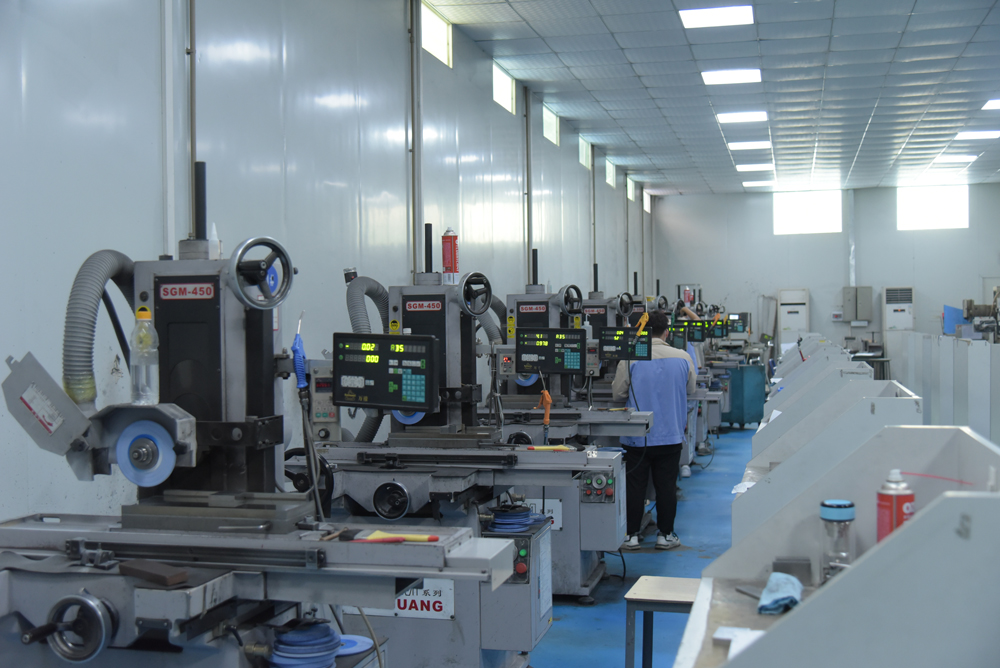
In daily mold engineering, the gap between a design that looks good on paper and one that performs reliably on the shop floor often comes down to structural details. A typical injection mold, for instance, must balance parting line selection, cooling channel layout, and ejection force distribution. From experience, a poorly placed parting line can increase flash by 0.02–0.05 mm on a 200-ton press, which directly affects cycle time and rework cost. Similarly, cooling channel diameter should stay within 8–12 mm for standard steel grades like P20 or H13, and the distance between channels should not exceed five times the channel diameter to avoid hot spots. These are not theoretical numbers—they come from real trials where cavity surface temperature variation was reduced from 18°C to 6°C simply by re-routing the baffles and bubblers.
On the process side, engineers must also pay close attention to shrinkage and warpage compensation. For a 30% glass-filled nylon part, the mold shrinkage can range from 0.3% to 0.7% depending on wall thickness and gate location. A common mistake is using a single shrinkage factor for the entire cavity; instead, we often split the cavity into zones and apply different shrink values based on flow direction and rib density. In one case, adjusting the gate from a side edge to a center fan gate cut the flatness deviation from 0.45 mm to 0.18 mm on a 150 mm-long bracket. Also, venting depth should be set at 0.02–0.03 mm for crystalline resins and 0.01–0.02 mm for amorphous ones—too deep and you get flash, too shallow and you get burn marks. These process parameters are not optional; they define whether a mold runs stable for 500,000 cycles or fails after 50,000.
Assembly and tryout are where the real “hard work” shows. A mold with perfect machining but poor alignment will still produce scrap. We always check guide pillar clearance—typically 0.02–0.03 mm for a standard two-plate mold—and use a dial indicator to verify platen parallelism within 0.01 mm per 100 mm. During tryout, record injection pressure, melt temperature, and hold time for every shot; this data becomes the baseline for future troubleshooting. If you are sourcing a new mold or improving an existing one, always ask the supplier for a detailed cooling analysis and a shrinkage simulation report. For more mold sourcing information and practical case studies, visit MoldWorld at www.moldw.com—it’s a solid resource for engineers who want to stay sharp on both structure and process.