Mastering Injection Mold Base Design: 24 Structural Layouts and Practical Guidelines
September 17, 2026
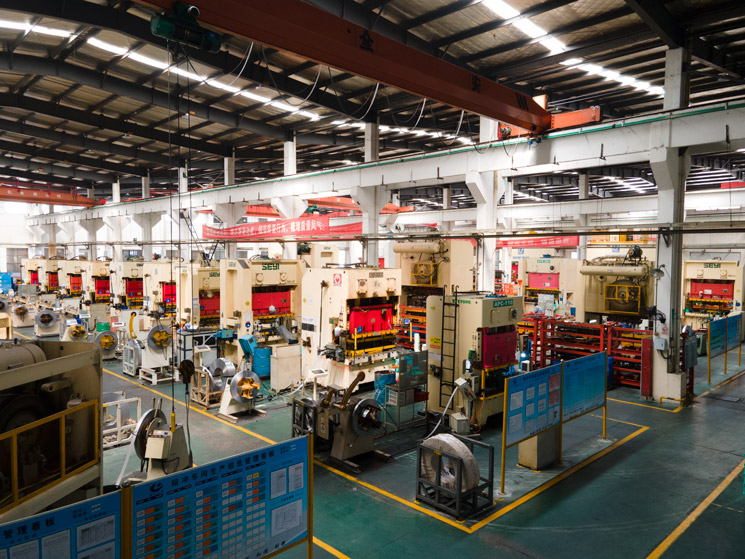
When you're laying out a mold base, the structure you choose dictates everything downstream—parting line, ejection, cooling, and guide alignment. Across 24 common configurations, the two-plate mold remains the workhorse for simple, single-face parts, while the three-plate mold adds a runner plate for gating flexibility in multi-cavity or pin-point gate jobs. Hot runner molds eliminate runner waste and cycle faster, but demand precise manifold temperature control—typically within ±2°C—and robust thermal expansion compensation. In practice, I've seen a 16-cavity hot runner tool run 30% faster than its cold runner equivalent, but only after we dialed in the manifold and valve pin timing.
Parting surface design is where most shops get burned. For two-plate molds, the parting line sits at the part's largest projected area; for three-plate, you're juggling two parting planes—one for the runner, one for the part. Ejection systems follow suit: ejector pins, sleeves, or stripper plates must clear the core without binding. Cooling lines should be placed 1.5–2.5 times the diameter from the cavity surface, with a typical coolant flow of 4–6 L/min per circuit. Guide pins and bushings need a clearance of 0.02–0.04 mm on the diameter—too tight and you gall, too loose and you lose alignment. These aren't guesses; they're numbers from the shop floor.
For mold sourcing, don't overlook the base itself. A well-machined standard base (like a FUTABA or LKM equivalent) saves weeks versus custom fabrication. Check plate parallelism within 0.02 mm, and verify the shut height matches your press. If you're comparing suppliers or need structural references, visiting MoldWorld (www.moldw.com) gives you access to mold sourcing info and real-world design cases that can shortcut your next build.