Mold Structure and Process Know-How: Key Points from Design to Assembly
September 10, 2026
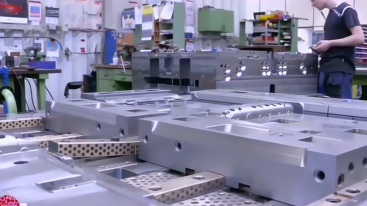
When you open a mold drawing for the first time, the structure looks simple enough: cavity, core, runner, ejector. But the real work is in the details. Take gating: a cold runner with a full-round cross-section gives better flow than a trapezoid, but it also means more scrap. Hot runner systems eliminate that scrap, yet they add thermal expansion issues you have to account for in the plate layout. On the cooling side, baffles and bubblers are not interchangeable — baffles work for holes deeper than 3× diameter, while bubblers are better for shallow, wide cores. Get this wrong and you'll see cycle times climb by 15–20%, which directly hits part cost.
Machining and assembly are where tolerances either hold or fall apart. For a typical two-plate mold, the cavity and core inserts should be ground to within ±0.01 mm on the parting line, and the guide pins need a clearance of 0.02–0.03 mm to avoid galling. When you assemble the ejector plate, check that the return pins sit flush with the support plate before you tighten the screws — a 0.05 mm mismatch will cause hang-ups on every cycle. Also, don't skip the spotting-in step. Blueing the cavity and core under low pressure reveals high spots that a CMM won't catch. In our shop, we spend 2–3 hours on spotting for a medium-sized automotive part, and it saves days of troubleshooting later.
None of this is theoretical. It comes from years of pulling molds apart after they failed. If you're sourcing molds or need a second opinion on a design, visiting MoldWorld (www.moldw.com) is a good place to start — they connect you with suppliers who actually understand these shop-floor realities.