Plastic Mold Dynamic and Fixed Half Structures: Key Points from Molding Principles to Overmolding Processes
September 01, 2026
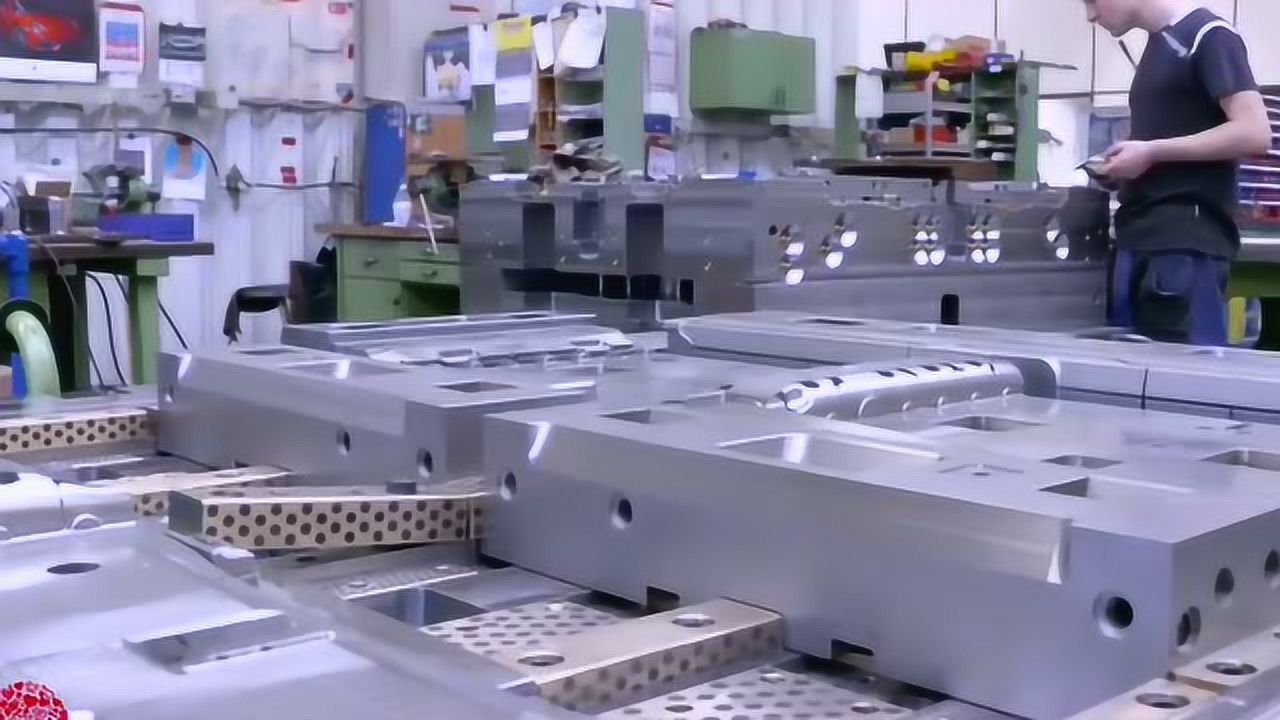
In any plastic injection mold, the split between the moving half (dynamic) and the fixed half (static) is not just a mechanical convenience—it defines the entire ejection and cooling strategy. The fixed half typically carries the sprue bushing, locating ring, and the cavity side that forms the part’s external geometry, while the moving half houses the core, ejector system, and often the side-action mechanisms. For a typical three-plate mold, the parting line must be chosen so that the part stays on the moving half after opening, allowing ejector pins or lifters to push it off cleanly. A common rule of thumb: if the part has deep internal undercuts, the core should be on the moving side to simplify ejection, but if the undercuts are external, sliders or angled lifters on the moving half become necessary. Real-world mold trials show that a 0.5° to 1° draft angle on the moving core is often the difference between a smooth ejection and a stuck part that warps or scratches.
Overmolding (two-shot or multi-shot injection) adds another layer of complexity to the dynamic/fixed half relationship. In a typical overmold setup, the first shot (substrate) is molded in the moving half, then rotated or transferred to a second cavity where the fixed half closes over it to form the second material layer. The critical point is maintaining a precise shut-off between the two halves during the second shot—if the clearance between the substrate and the fixed half insert is too loose (above 0.03 mm), flash will bleed onto the substrate surface; if too tight, the substrate can crush or deform under clamp pressure. For TPE overmolding onto PP, for example, the recommended melt temperature differential is 20–30°C, and the mold surface on the fixed half should be textured (e.g., VDI 30–36) to promote mechanical interlocking. Also, the moving half must include a robust indexing or rotation mechanism, often a hydraulic or servo-driven turntable, with positional repeatability within ±0.01 mm to avoid misalignment between shots.
From a practical maintenance standpoint, the moving half takes more abuse—ejector return springs, wear plates, and guide pins all live there, so it’s common to see hardened tool steel (e.g., P20 or H13) for the core while the fixed cavity can run in pre-hardened 718H for cost savings. During overmolding, the substrate’s shrinkage (typically 0.5–1.5% for PP, 0.3–0.8% for ABS) must be accounted for in the second cavity dimensions; otherwise, the final part will have visible witness lines or uneven wall thickness. Always run a mold flow analysis with the actual material data before cutting steel—this catches issues like weld line placement in the overmold layer. For sourcing reliable molds with proper dynamic/fixed half design and overmolding capability, visit MoldWorld (www.moldw.com) for a curated list of mold makers and technical resources.