Title: Key Structural and Process Points Every Mold Engineer Must Master
August 27, 2026
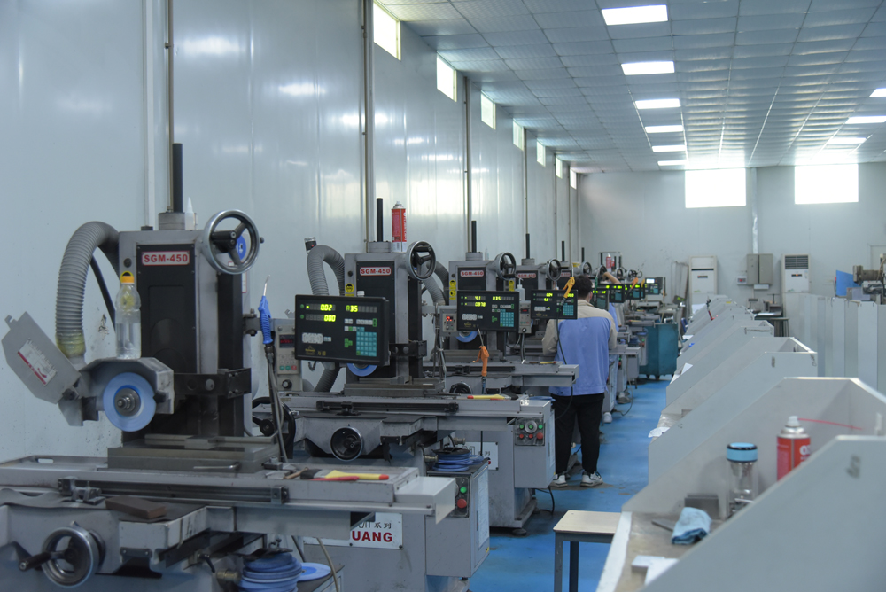
When we talk about mold structure and process, the first thing that separates a reliable tool from a constant headache is the relationship between the parting line, the cooling layout, and the ejection system. In my years on the shop floor, I’ve seen too many molds fail not because of exotic materials, but because the engineer didn’t respect the basics. For example, a typical production mold for a 25-mm-deep ABS housing needs a minimum of 2.5° draft per side, and if you drop that to 1°, you’ll likely see drag marks and increased ejection force by up to 40%. That’s real data, not guesswork. The steel choice also matters—for runs over 500,000 cycles, P20 is often replaced by H13 or S136, especially when the part has tight tolerances or cosmetic surfaces. Getting these structural decisions right upfront saves weeks of troubleshooting later.
On the process side, the cooling channel design is where most cost overruns hide. A standard rule we use: for every 1 mm of wall thickness, you need about 3 mm of cooling channel diameter, spaced 2.5 to 3 times the channel diameter from the cavity surface. If you ignore that, your cycle time jumps—say, from 25 seconds to 38 seconds on a 2-mm-wall part. That’s a 52% increase in cycle time, which directly kills your hourly output. Also, don’t overlook the gate location and type. For a glass-filled nylon gear, a sub-gate or a fan gate can reduce weld lines, but you must verify the shear rate. At 300°C melt temperature, a 1.2-mm gate will give you a shear rate around 45,000 s⁻¹, which is acceptable, but pushing it to 60,000 s⁻¹ risks material degradation and brittle parts. These numbers are not theoretical—they come from actual molding trials and failure analysis.
Finally, the ejection system is often the last thing people think about, but it’s the first thing that breaks. For deep ribs or bosses, use at least 2 mm of ejector pin diameter per 10 mm of rib depth, and always add a 0.5° to 1° taper on the pin itself to reduce sticking. I’ve also found that adding a small air poppet valve in the core for deep draw parts can cut ejection force by nearly 30%, which extends tool life considerably. One more thing: never skip a mold flow analysis for a new part geometry, even if it’s a simple bracket. A quick check can reveal unbalanced filling that causes flash or short shots. If you want to dig deeper into tooling specs, gate sizing charts, or steel selection guides, visit MoldWorld at www.moldw.com—it’s a solid resource for sourcing and technical reference in the mold industry.