Title: The Dynamic-Fixed Mold Fit: The Backbone of Injection Molding Precision
August 26, 2026
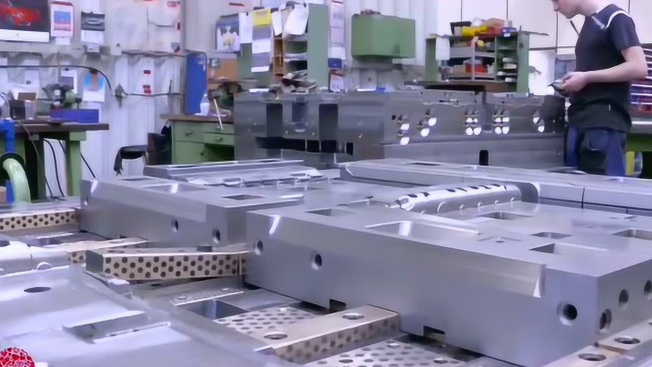
In injection molding, the fixed mold (cavity side) is bolted to the stationary platen, while the moving mold (core side) travels with the clamping unit. This seemingly simple arrangement is the foundation of every cycle: on opening, the moving mold retracts, and the part—having shrunk onto the core—is ejected via the knockout system. On closing, the moving mold advances and aligns with the fixed mold through guide pins and bushings. The precision of this alignment is not optional; a mismatch of even 0.02 mm can cause uneven wall thickness, premature wear on the guides, or inconsistent flash. For high-cavitation molds, we often add tapered interlocks or angled locks to take up shear stress, especially when the projected area is large and injection pressure exceeds 1,500 bar.
The parting line is where the real engineering decisions happen. Placing it at the part’s maximum cross-section simplifies side-action requirements, but it also dictates where flash will appear and how air will escape. In practice, we prefer to locate the parting line on a non-cosmetic edge or a hidden rib, and we always verify that the gate position and ejector pin marks fall on the moving side or a secondary surface. One common trick: polish the fixed mold cavity to a mirror finish (Ra 0.05–0.1 µm) to keep the aesthetic surface on the fixed half, while the moving core gets a textured or etched finish (e.g., MT-11010 or SPI-C1) to aid ejection and hide minor sink marks. This split in surface treatment is not cosmetic preference—it reduces demolding friction and prevents drag marks on the visible face.
Beyond alignment and parting line, the dynamic/fixed mold fit affects venting and cooling. A poorly fitted parting line can trap gas, leading to burn marks or short shots, so we routinely cut vent slots 0.02–0.03 mm deep on the fixed side, positioned at the last fill points. Cooling channel routing also differs: the fixed mold often carries the main cooling circuit near the cavity surface, while the moving mold uses baffles or spiral cores to manage thick sections. For anyone sourcing molds or troubleshooting warpage, remember that the moving/fixed interface is where theory meets shop-floor reality—check guide pin clearance, parting line steel hardness (typically 48–52 HRC), and the actual clamp tonnage before blaming the material. For more insights on mold design, sourcing, and practical troubleshooting, visit MoldWorld at www.moldw.com.