Title: Core and Cavity in Plastic Injection Molds: Structural Logic and Overmolding Essentials
August 26, 2026
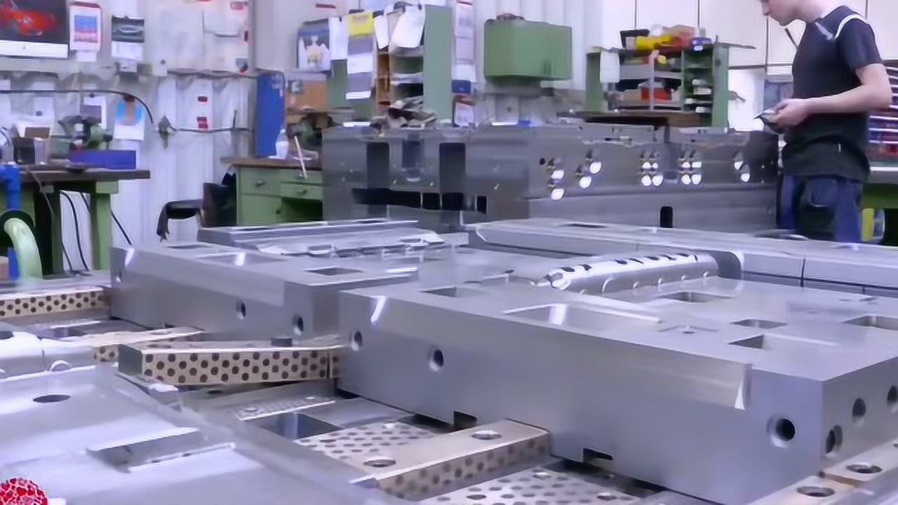
In any plastic injection mold, the split between the moving half (ejection side) and the fixed half (nozzle side) is not just a mechanical convenience—it defines the entire molding sequence. The fixed half carries the sprue bushing, locates the nozzle, and typically holds the cavity (or core, depending on part geometry). The moving half houses the ejector system and, in most two-plate designs, pulls the part away from the fixed half during opening. For a part with external undercuts, sliders are mounted on the moving half, while internal undercuts require lifters or collapsible cores. A rule of thumb we use: always place the largest projected area on the fixed half to minimize deflection during clamping, and design the parting line so that the part naturally stays on the moving side. This avoids forced ejection and reduces cycle time by 10–15% in high-cavitation molds.
When moving to overmolding—especially rubber over plastic (e.g., TPE over ABS or PA)—the structural logic shifts. The first-shot plastic substrate must be fully cured and dimensionally stable before the second shot. In a rotary table or index plate mold, the substrate is transferred from the fixed half to the moving half, and the cavity for the rubber layer is cut into the opposite side. Critical here is the shut-off clearance: a 0.02–0.05 mm interference between the substrate and the second cavity edge prevents flash, but too much interference crushes the plastic. We also control the rubber injection temperature (typically 170–190°C for TPE) and hold pressure (30–60 MPa) to avoid washing out the first-shot geometry. For parts with thin rubber walls (0.5–1.0 mm), we add a cold slug well and a fan gate to reduce flow marks, and we always verify adhesion via a 90° peel test—if the peel force drops below 1.5 N/mm, we adjust the substrate surface treatment (flame or plasma) before blaming the material.
Another practical point: venting in overmold cavities is often underestimated. Rubber compounds trap air more easily than thermoplastics, so we cut 0.01–0.02 mm deep vents on the parting line, 3–5 mm wide, spaced every 10–15 mm around the cavity. If you see burn marks or incomplete fill, check the vent depth first—most shops set them too shallow. Also, when designing the moving half for overmolding, remember that the ejector pins must clear the substrate’s ribs or bosses, or you risk bending them during ejection. In our shop, we always run a mold flow analysis on the first-shot shrinkage (PA6+30% GF shrinks 0.3–0.5%, ABS about 0.5–0.7%) to predict the substrate’s final dimensions before cutting the second cavity. For more detailed mold sourcing and design guidelines, visit MoldWorld (www.moldw.com)—they have a good library of real-world mold breakdowns and supplier comparisons.