Injection Mold (Mold Base) Structural Design: Engineering Insights on 24 Typical Configurations
August 09, 2026
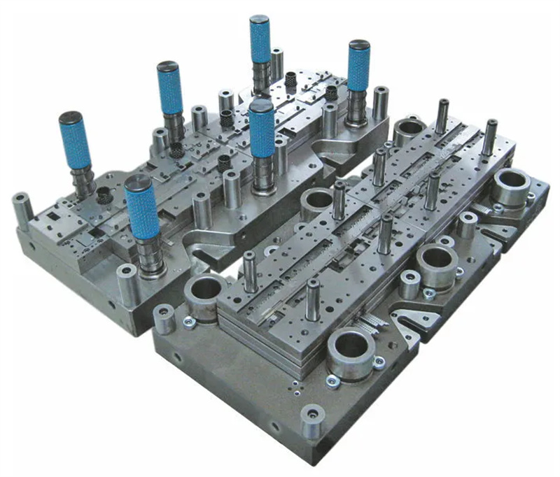
When we talk about mold base design, we’re not just picking a standard size from a catalog. The 24 typical configurations covered here represent the most common engineering solutions we encounter in daily tooling work—from two-plate and three-plate systems to more complex stack molds and hot runner variants. Each layout directly impacts cycle time, part quality, and maintenance ease. For instance, a standard two-plate mold with a direct sprue is still the most cost-effective for low-cavitation runs, but once you exceed 8 cavities or need center gating, a three-plate design becomes necessary—even though it adds about 15% to the base cost and increases opening stroke by 40–60 mm. The real trick is matching the ejection method: for deep ribs or bosses, you’ll want a combination of ejector pins and lifters, but if you have undercuts, a slide system with angled pins (typically 15–25° of travel) will dictate the parting line and overall base thickness.
One of the most overlooked aspects in these 24 schemes is the cooling circuit layout relative to the mold base’s standard plate thickness. For a 2020 mold base (200×200 mm), you can typically fit 8 mm cooling channels with a 5 mm pitch, but if you switch to a 3030 base, you can go to 10 mm channels and reduce cooling time by up to 22%—assuming you use baffles or spiral cores for deep cavities. On the ejection side, remember that the return stroke force on a 50 mm ejector plate is roughly 10–15 kN, so if you’re using hydraulic cylinders for early core pull, you need to verify the base’s clamping slots can handle that lateral load. Also, for high-production molds, standard DME or HASCO bases with pre-hardened 28–32 HRC plates are fine, but for abrasive materials like glass-filled nylon, you’ll want to specify hardened guide pillars and bushings (58–60 HRC) to avoid premature wear.
In practice, I always tell junior designers to start with a proven 24-configuration chart and then modify only one variable at a time—change the gate type, then test the fill, or change the ejector layout, then check for part warp. A common mistake is over-engineering: adding a hot runner to a 4-cavity mold for a simple bracket part when a cold runner with a sub-gate would save 30% in tooling cost. But if you’re dealing with a thin-wall part (0.8 mm) or a high-gloss surface, a hot runner with valve gates is non-negotiable. The key is to document your base selection rationale—steel grade, plate thickness, and guide system—so the next engineer can reproduce your logic. For more detailed mold sourcing and structural examples, visit MoldWorld (www.moldw.com) where you can compare standard base suppliers and get real quotes for your next project.