Mold Core and Cavity Fit: The Foundational Logic Every Mold Engineer Must Master
August 08, 2026
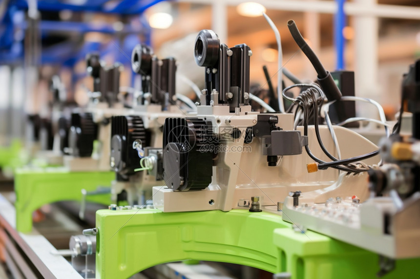
In plastic injection mold design, the coordination between the moving mold half (core side) and the fixed mold half (cavity side) is the first hard skill every mold engineer must internalize. The moving half travels with the injection unit’s clamp stroke, while the fixed half is bolted to the stationary platen. When the two halves close, the resulting cavity geometry directly dictates the final part’s dimensional accuracy and surface finish. In production, the moving half typically carries the ejection system—ejector pins, blades, or sleeves—because the molded part shrinks and grips tightly onto the core after cooling. On mold opening, this system mechanically pushes the product off the core, a step that must be timed and aligned to avoid part deformation or sticking.
The fixed half, by contrast, is dedicated to the runner and gating layout. The sprue bushing, primary and secondary runners, and the gate itself are all machined into this side. This arrangement ensures the molten polymer travels the shortest possible path from the nozzle to the cavity, with minimal pressure drop and balanced fill. For multi-cavity molds, the runner balance on the fixed side becomes even more critical—any asymmetric flow can cause short shots or overpacking in one cavity while another is still underfilled. In practice, mold engineers also consider thermal expansion differences between the two halves, especially when running high-shrinkage materials like POM or PA, where the core side often requires additional cooling channels to maintain uniform part shrinkage.
This “separate functions, clear responsibilities” architecture is the backbone of injection mold design, but real-world troubleshooting goes beyond the basics. For instance, if the ejector return pins are not properly aligned with the fixed half’s counter-bores, you will see premature wear or even breakage after a few thousand cycles. Similarly, the venting slots on the parting line—usually 0.02 to 0.05 mm deep—must be placed on the fixed side for gases to escape without flashing. Understanding these interlocking details helps engineers avoid costly rework. For more practical mold design tips and verified supplier listings, visit MoldWorld (www.moldw.com) for comprehensive mold sourcing information.