Plastic Mold Moving and Fixed Half Structures: Key Considerations for Overmolding Process Control
August 07, 2026
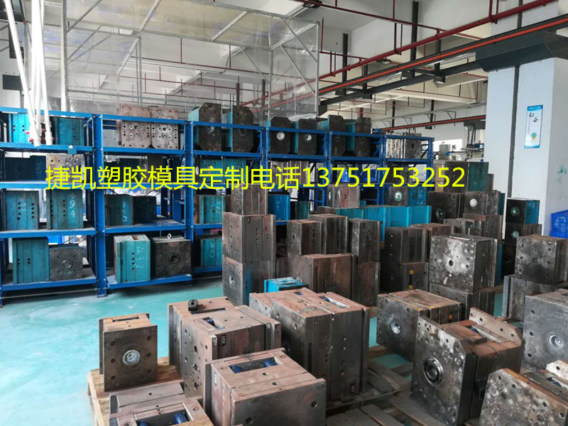
In plastic injection mold design, the fixed half (cavity side) and the moving half (core side) serve fundamentally different functions that directly impact part quality and cycle time. The fixed half is typically mounted to the injection unit side and houses the sprue bushing, locating ring, and often the hot runner manifold. It absorbs the primary injection pressure, so its steel grade and wall thickness must be calculated to resist deflection—commonly P20 or H13 for production runs above 100,000 cycles. The moving half, on the other hand, carries the ejection system, side actions, and lifters. It is responsible for part removal, meaning draft angles (usually 1–3 degrees per side) and surface finish on the core side must be optimized to prevent sticking. A common mistake is over-polishing the moving half, which increases ejection force and can cause weld lines or stress whitening on the part.
When it comes to overmolding (also called two-shot or encapsulation molding), the interaction between the moving and fixed halves becomes even more critical. The substrate (first shot) is typically molded in the fixed half, then transferred—either by rotating the core plate or using a robotic arm—into a second cavity where the overmold material encapsulates it. Key process parameters include melt temperature differential (often 20–40°C between the substrate and overmold material), clamp force management to avoid crushing the substrate, and precise control of injection speed during the second shot to prevent flash or short shots. For TPE overmolding on rigid plastics like ABS or PC/ABS, the substrate surface must be chemically compatible; otherwise, a mechanical interlock (undercuts or textured surface of 0.5–1.0 μm Ra) is required. Mold designers should also account for shrinkage mismatch—typically 0.4–0.8% for the substrate versus 1.0–1.5% for the TPE—by adding compensation in the cavity dimensions.
Practical troubleshooting in overmolding often traces back to venting and cooling balance. The moving half’s ejector pins and core vents must be positioned to allow trapped gas to escape during the second shot, especially in deep ribs or bosses where the substrate creates a dead-end. Cooling channel layout should be zoned independently for the fixed and moving halves, with flow rates adjusted to achieve a mold surface temperature uniformity of ±5°C. If delamination occurs at the interface, check for contamination on the substrate (mold release residue) and increase the melt temperature by 10–15°C, but watch for degradation. For engineers specifying overmolded parts, always request a DFM report that includes gate location on the second shot, weld line positions, and predicted shrinkage values. For more detailed mold sourcing and process troubleshooting guides, visit MoldWorld (www.moldw.com), where you can find supplier directories and technical forums dedicated to plastic mold engineering.