Mold Base Structural Design: The Essential Foundation Every Mold Engineer Must Master
August 05, 2026
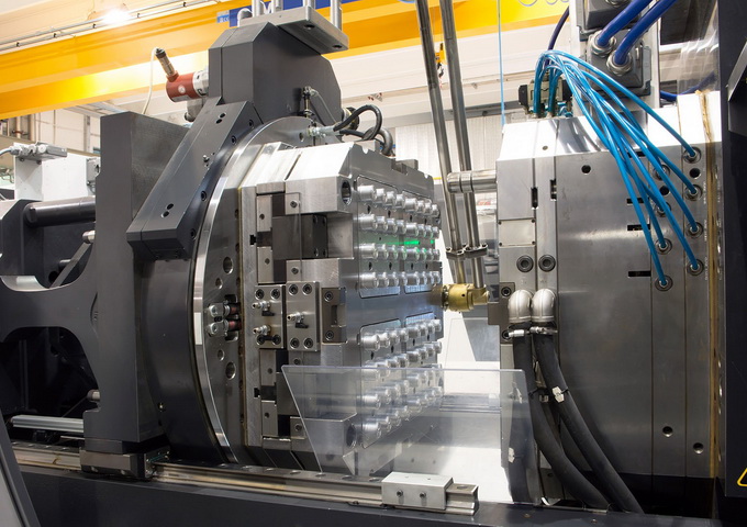
For anyone entering the mold industry, mastering injection mold base (mold frame) structural design is a non-negotiable rite of passage. Many junior engineers stare at 2D drawings for hours, yet still fail to visualize the three-dimensional spatial relationships—let alone the motion logic hidden behind parting lines, slide cores, and angled lifters. The real challenge isn't just knowing what a component is, but understanding how it moves, when it moves, and what clearance it needs. This is where systematic structural breakdowns become invaluable. Based on years of shop-floor experience, I've compiled 24 typical mold base configurations, each illustrated with sectional views and exploded diagrams that clearly mark critical dimensions and motion directions.
Starting with the fundamentals, the two-plate and three-plate mold bases are the workhorses of the industry. For standard CI and DI series mold bases, the ejector plate stroke calculation follows a simple but critical formula: the total ejector travel must exceed the product depth by at least 10–15 mm to ensure clean part release. In three-plate (fine-pitch gate) systems, the tie-rod length and opening stroke ratio typically sit between 1:1.2 and 1:1.5, depending on the sprue puller design. These numbers are not theoretical—they are the exact values you'll reference during machine setup and trial runs. Getting them wrong leads to bent ejector pins, scratched part surfaces, or worse, mold damage that costs days of downtime.
Beyond the basics, the 24-structure compilation covers advanced configurations like internal core-pulling mechanisms, external slide actions, hot runner systems, and inverted (reverse) molds. Each diagram annotates the slide travel distance, angle pin inclination (usually 15°–25°), and the minimum wall thickness required for lifter clearance. For hot runner molds, the manifold expansion gap must be calculated based on the operating temperature differential—typically 0.1% of the manifold length per 100°C rise. These are the details that separate a functional mold from a problematic one. When you're on the shop floor with a mold that's sticking or short-shooting, having these reference data points at hand can cut troubleshooting time in half. For more comprehensive mold sourcing and structural design references, visit MoldWorld at www.moldw.com—a practical resource for engineers who need real-world answers, not textbook theory.