Title: 24 Proven Frame Configurations for Injection Mold Design and Shop-Floor Practice
August 05, 2026
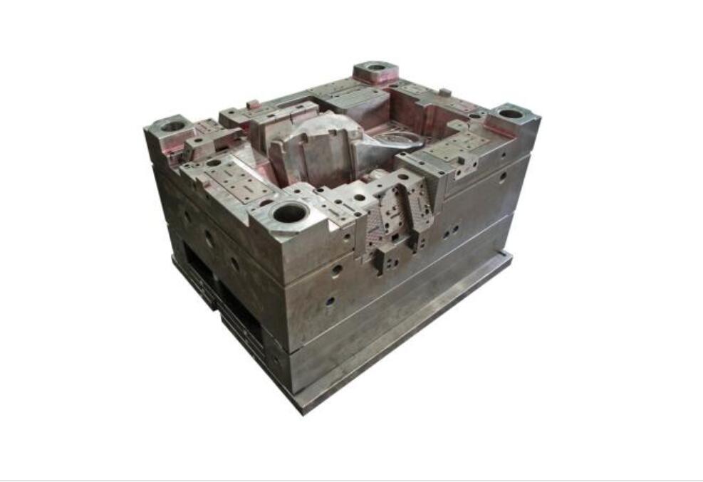
When we talk about injection mold base design, the first thing that matters is not creativity but predictability. Over the years, our shop has standardized on 24 typical frame configurations, each matched to specific part geometry and production volume. For instance, the two-plate mold with a straight ejector system remains the workhorse for shallow-draft parts up to 300 mm in length, where we keep the ejector stroke at 1.5 times the part depth to avoid sticking. For deep ribs or bosses, we switch to a three-plate design with a pin-point gate, but we always add a secondary puller plate to prevent the runner from flexing during the first 20 mm of opening. The key is to calculate the cavity pressure at the gate—typically 350 to 500 bar for ABS—and then size the support pillars so that the deflection stays under 0.03 mm per 100 mm of span.
Half of the issues we see on the floor come from neglecting the relationship between the mold base and the cooling circuit. In the 24 configurations, we never place water lines closer than 8 mm to the cavity surface, and we always use baffles or spiral cores for cores above 25 mm in diameter. For a typical 16-cavity family mold, we run 6 mm straight-through channels at 5°C below the melt temperature, which cuts cycle time by 18% compared to a parallel circuit. Also, for slides and lifters, we keep the return spring preload at 10% of the slide travel, and we machine a 0.5° taper on the heel block to avoid galling after 50k cycles. These numbers come from actual mold trials, not from simulation alone.
The last point is about maintenance and interchangeability. Every one of the 24 frame structures we use has a standard screw pattern and locating ring diameter—either 100 mm or 150 mm—so that we can swap bases between presses without re-cutting the mounting holes. We also harden the guide pins to 58 HRC and nitride the ejector plates to 65 HRC, which extends the service life to over 300k shots before re-grinding. In practice, if you follow these configurations and keep your tolerances within ±0.02 mm on the parting line, you will reduce rework by at least 30%. For more detailed frame drawings and sourcing of standard mold bases, visit MoldWorld at www.moldw.com—they have a solid database of supplier specs and machining guidelines.