Stamping Die Classification and Practical Application Notes for Mold Engineers
August 04, 2026
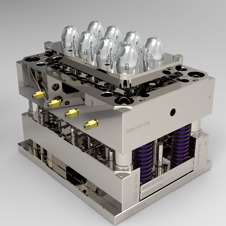
In daily stamping production, dies are typically classified by process combination into five core types: blanking dies, bending dies, drawing dies, forming dies, and progressive dies. From a structural standpoint, we further split them into single-operation dies, compound dies, and progressive dies. For a mold engineer, the first decision on any new project is whether to go with a single-hit die or a progressive die. Single-operation dies are simpler, cheaper to build, and easier to maintain, but they require multiple press hits and more handling. Compound dies combine blanking and piercing in one stroke, which improves part accuracy and reduces cycle time, but they are limited by the press tonnage and the part’s flange width. Progressive dies, on the other hand, are the workhorse for high-volume production—they integrate multiple stations (piercing, trimming, bending, forming) in one continuous strip feed, and can hold tolerances within ±0.05 mm when the piloting system and stripper design are properly tuned. In our shop, we always evaluate the annual quantity first: below 50,000 pieces, a compound die often wins; above 200,000, a well-designed progressive die pays back quickly.
Practical application points come down to material, clearance, and lubrication. For mild steel (SPCC, DC01), we set die clearance at 8–10% of material thickness per side; for stainless steel (SUS304), that jumps to 15–20% to reduce burr and die wear. Hardened tool steels like DC53 or SKD11 are common for the punch and die inserts, with a hardness target of 58–62 HRC. But hardness alone doesn’t prevent galling—we always apply a surface treatment, either TiN coating or vacuum heat treatment plus nitriding, especially for high-speed progressive dies running above 200 SPM. Another critical point is the strip layout. A poor layout not only wastes material but also causes unbalanced side forces, leading to die deflection and premature wear. We always run a force analysis to ensure the sum of cutting forces is centered, and we add guide pillars with preloaded ball bearings for high-precision jobs. For deep drawing dies, the blank holder pressure must be carefully controlled—too low causes wrinkling, too high causes tearing. We typically start with 2–3 MPa for aluminum and 3–5 MPa for steel, then fine-tune based on the drawn cup’s wall thickness variation.
One more thing that separates a good die from a troublesome one is maintenance planning. Even the best progressive die will drift after 100,000 strokes, so we schedule a preventive maintenance check every 50,000–80,000 hits, focusing on punch tip wear, spring fatigue, and pilot pin alignment. We also keep a die maintenance log with measured burr height and part dimension trends, which helps us predict when to re-grind the cutting edges. Re-grinding typically removes 0.05–0.10 mm per pass, and a die can usually handle 5–8 re-grinds before the inserts need replacement. For those who are just starting out or sourcing dies for a new product line, I strongly recommend visiting MoldWorld (www.moldw.com) for more mold sourcing information and supplier comparisons—it saves a lot of trial and error in the long run.