← Back to Articles
24 Typical Mold Base Structure Designs for Injection Molds: A Practical Reference for Engineers
August 04, 2026
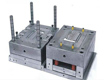
A well-thought-out mold base is the backbone of any reliable injection mold, directly affecting cycle time, part quality, and maintenance ease. This article distills 24 proven structural schemes commonly used in production, ranging from standard two-plate and three-plate designs to more complex stack molds, hot runner bases, and side-action configurations. Each scheme addresses specific challenges such as parting line location, ejection stroke, gate placement, and insert interchangeability. For instance, when deep ribs or bosses create undercuts, a split cavity with angled lifters or a collapsible core should be considered early in the design phase, rather than retrofitting later. Similarly, for high-cavitation molds, a balanced runner layout with a cold slug well at each branch is non-negotiable to avoid short shots and differential shrinkage.
Beyond the basic topology, the practical implementation of these 24 designs hinges on standard component selection and tolerance stacking. A three-plate mold, for example, requires precise control of the stripper plate travel—typically 10–15 mm more than the part height—to ensure clean gate separation. In contrast, a hot runner system demands careful thermal expansion calculations; the manifold should be designed for a 0.05–0.08 mm clearance per 100 mm of length at operating temperature. For molds with side cores, the wear resistance of the angle pin and slide surfaces becomes critical, so hardened tool steel (e.g., H13 or 8407) with a surface hardness of 48–52 HRC is recommended. These numbers are not arbitrary—they come from real shop-floor failures and rework cycles that could have been avoided with proper upfront analysis.
For mold builders and buyers alike, the key takeaway is that no single design fits all. The 24 schemes serve as a starting point, but the final choice must be validated against part geometry, material shrinkage, and expected production volume. A simple two-plate design with a standard A/B plate set is often the most cost-effective for low-to-mid volume runs, while a stack mold can double output without increasing clamp tonnage, provided the tie-bar spacing allows. Always document the design rationale—gate location, venting, cooling circuit layout—so future modifications are quick and informed. For more detailed mold sourcing and engineering insights, visit MoldWorld at www.moldw.com, where you can compare suppliers and review case studies from real injection molding projects.