Injection Mold Structure Design: From Frame Selection to Process Execution—Key Details That Decide Success
September 03, 2026
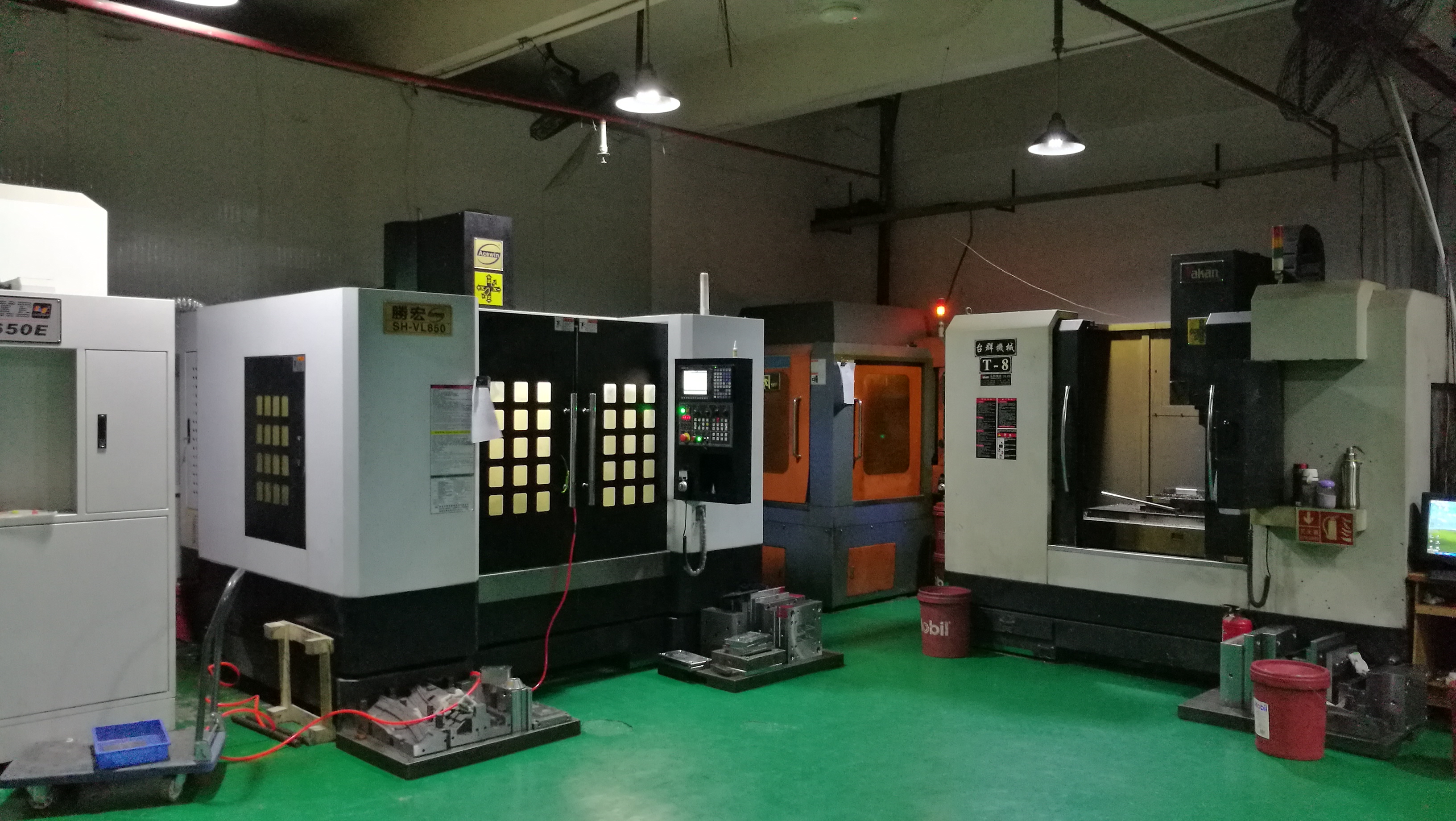
When we sit down to design an injection mold, the first decision—frame selection—sets the tone for everything that follows. For a typical 200-ton machine, we often start with a standard 3535 or 4040 frame, but the real engineering begins when we calculate the required clamping force against projected area and cavity pressure. A common mistake is oversizing the frame for safety, which drives up material cost and machining time. Instead, I prefer to map out the parting line first, then use a conservative cavity pressure of 600–800 bar for general ABS or PP parts, adjusting for wall thickness and flow length. This gives us a realistic frame size that balances rigidity with economy. Also, don’t forget to check the ejector plate stroke against the part’s draft angle—if you have deep ribs, you’ll need additional ejector pins or a lift mechanism, which changes the frame’s standard ejector layout.
Once the frame is locked, the insert design and cooling channel routing become the true battleground for cycle time. For a part with a 2.5 mm nominal wall, we typically aim for a cooling time of 8–12 seconds, but that only happens if we use baffles or spiral cores in deep boss areas. I always run a mold flow analysis early—not just for fill, but for temperature distribution. If the hot spot exceeds 15°C variation across the cavity, I’ll add additional cooling circuits or switch to a high-thermal-conductivity copper alloy for those inserts. On the steel side, for production runs above 500,000 parts, P20 with nitriding is fine, but for glass-filled materials, I specify H13 or S136 with a hardness of 48–52 HRC to avoid wear at the gate and parting line. These choices directly affect the quote: a hardened insert adds 10–15% tool cost but can cut per-part cost by 20% due to reduced maintenance.
Finally, process execution is where design intent meets reality. I always specify a two-stage ejection sequence if the part has undercuts or fragile features—this avoids deformation that shows up as visible sink marks or warpage. Gate location is another detail that can make or break a job; for a cosmetic surface, I place the gate on a non-visible edge or use a sub-gate that gets trimmed in the mold, but this adds a secondary operation. In my experience, the best quoting practice is to include a 5–8% contingency for mold trials and minor steel adjustments, because even with thorough analysis, real-world shrinkage can vary by 0.1–0.2% depending on the batch of resin. For anyone looking to refine their mold sourcing or compare design standards across suppliers, I recommend checking out MoldWorld (www.moldw.com) for practical data on frame sizes, steel grades, and cooling best practices—it’s a solid reference before you commit to a quote.