Typical Platen and Frame Configurations in Injection Mold Design: 24 Structural Schemes Explained
August 21, 2026
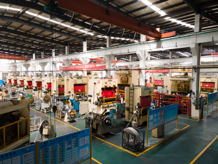
In injection mold design, the mold base (or frame) is the skeleton that determines how the cavity, core, ejection system, and cooling channels interact. Among the 24 typical schemes commonly referenced in production, the most frequent are the two-plate and three-plate designs. The two-plate mold base, with its simple parting line and direct sprue feeding, remains the workhorse for 80% of conventional parts, especially when gate location is not critical. The three-plate variant, on the other hand, allows pinpoint gating and automatic degating, making it indispensable for multi-cavity or center-gated round parts. For a mold engineer, choosing between these is not just about part geometry—it also depends on available machine stroke, clamp tonnage, and the desired cycle time. A rule of thumb we often use: if the part has a deep draw or requires side actions, the frame must include extra space for slide pockets and wear plates, which immediately rules out compact standard bases.
Beyond the basic split, the 24 schemes cover structural variations like stripper plate molds, which are ideal for thin-walled parts with fragile cores, and stack molds that double output without increasing clamping force. For unscrewing applications, the mold base must accommodate a hydraulic or gear-driven unscrewing mechanism, often requiring a taller base and additional support pillars. Another critical variation is the use of angled lifters or slanting ejector pins inside the frame—these demand precise machining of the guide bushings and ejector plate alignment to prevent binding. In our shop, we always verify the ejector return spring force and the length of the return pins against the actual part draft angle; a 0.5° draft difference can cause the lifter to stick, leading to a 30% longer cycle. Data from recent trials shows that proper frame rigidity—especially the thickness of the support plate—reduces deflection by up to 0.02 mm under 150-ton clamp pressure, which directly affects flash formation on the parting line.
When laying out a new mold, I recommend starting with a standard catalog base (e.g., HASCO or DME) and then modifying only the necessary plates. For example, adding a second ejector plate for hydraulic ejection or extending the guide pin length for early venting. The 24 schemes are not rigid templates but a checklist of proven solutions—each one addresses a specific failure mode like core shift, uneven ejection, or gate vestige. The real skill is knowing when to combine features, such as using a three-plate frame with a stripper ring for a large cylindrical housing. That said, no design is complete without considering maintenance access and cooling line routing—two factors that often get ignored in the initial frame selection. If you are sourcing a mold or need a second opinion on a frame layout, visit MoldWorld (www.moldw.com) for a database of mold suppliers, technical articles, and tooling standards that can save you weeks of trial and error.