Title: Stamping Process Fundamentals: A Practical Breakdown of Operations, Materials, and Dies
August 16, 2026
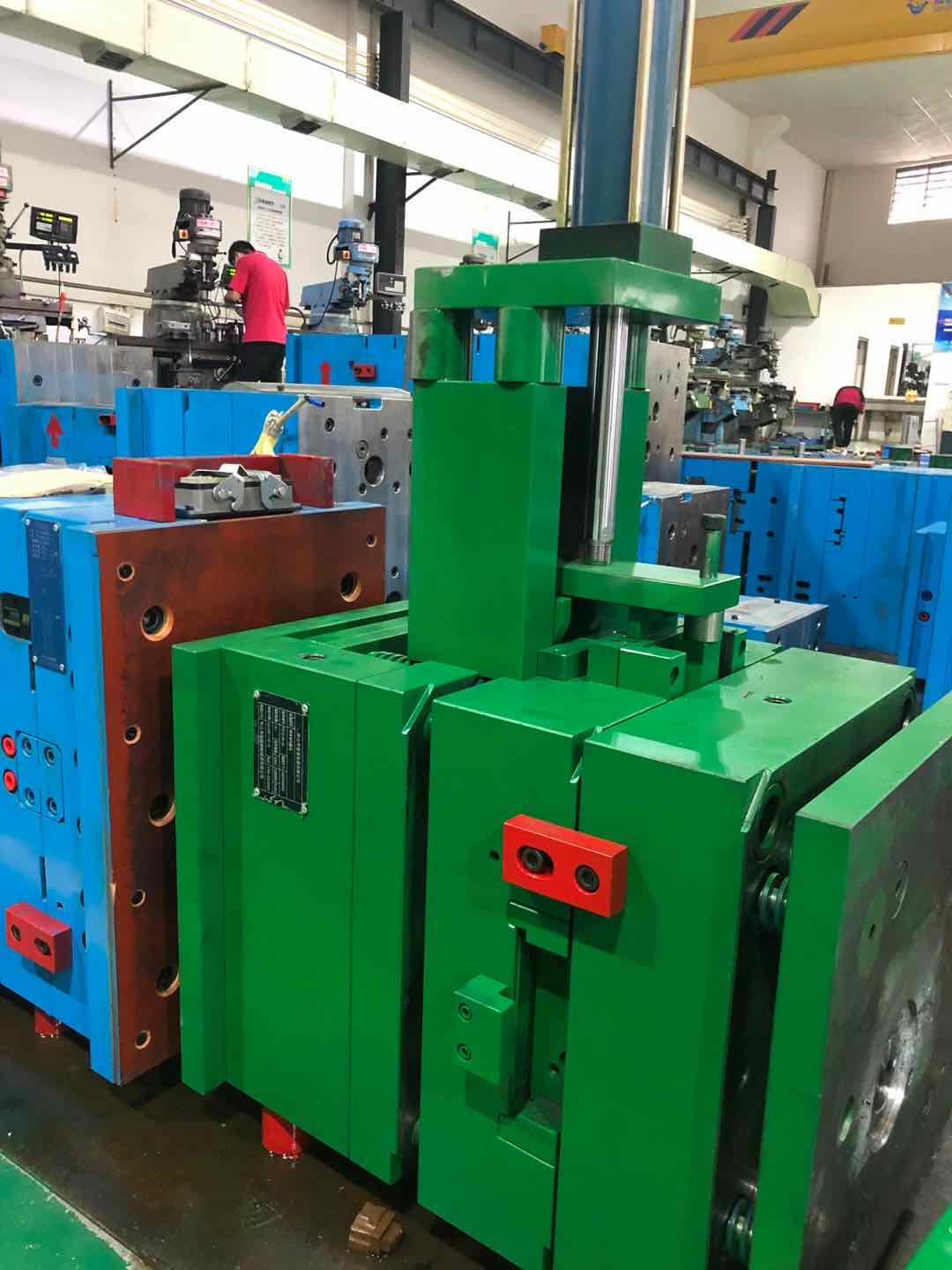
In daily stamping production, the choice of process sequence directly dictates part quality and tool life. The four basic operations—blanking, bending, drawing, and forming—each impose distinct stress states on the material. For instance, blanking relies on shear fracture, where the clearance between punch and die typically ranges from 5% to 10% of material thickness for mild steel, affecting burr height and dimensional accuracy. Bending requires careful consideration of springback, often compensated by over-bending angles of 2° to 5° depending on tensile strength. Drawing, meanwhile, demands a blank holder force set at roughly 20% to 30% of the drawing force to prevent wrinkling, while the punch radius should not be less than 3 to 5 times the sheet thickness to avoid tearing. A practical rule from the shop floor: always simulate the strip layout first, as material utilization below 70% usually signals an opportunity to redesign the process sequence.
Material selection is where many mold issues originate. For low-carbon steels like DC01 or SPCC, the elongation at break is typically above 28%, making them suitable for moderate drawing. However, high-strength steels (e.g., DP780) exhibit lower ductility and higher springback, requiring die surfaces with increased relief angles and stronger nitrogen gas springs for pressure control. Aluminum alloys like 5052 or 6061 have a lower elastic modulus—about one-third of steel—so die clearances must be tightened by 0.02 to 0.05 mm to maintain edge quality. Also, never overlook the influence of surface roughness: a die polished to Ra 0.4 µm reduces friction and galling, extending maintenance intervals by up to 40%. In practice, always verify the material certificate’s yield strength and hardness, as batch-to-batch variation in hardness by 10 HV can shift the optimal punch-die clearance by 0.01 mm.
Die construction details matter more than most CAD models suggest. For progressive dies, the pilot pin diameter should be at least 1.5 times the material thickness, and the pilot hole tolerance kept within ±0.01 mm to ensure consistent indexing. When designing draw dies, the draw bead height should be set at 0.8 to 1.2 times the sheet thickness, with a radius of 4 to 6 mm, to control material flow without excessive thinning. Regular maintenance—checking wear on cutting edges every 50,000 strokes and re-lubricating guide bushings every 10,000 strokes—can reduce unplanned downtime by 25%. If you are sourcing new dies or troubleshooting existing ones, visiting MoldWorld (www.moldw.com) provides access to verified mold suppliers, technical forums, and case studies that bridge the gap between theory and shop-floor reality.