Plastic Mold Core and Cavity Structure Analysis and Overmolding Process Essentials
August 13, 2026
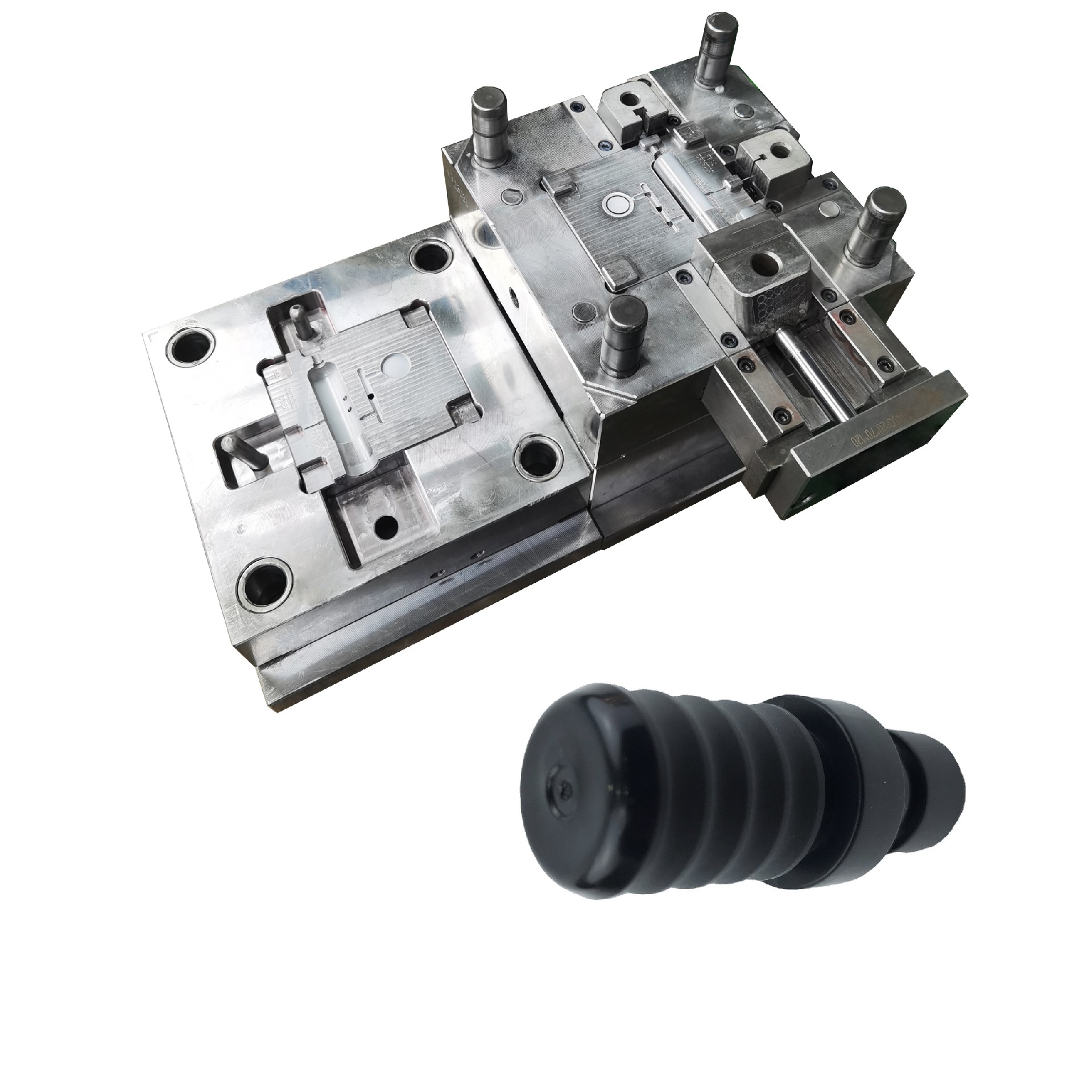
In plastic injection mold design, the moving mold (core side) and fixed mold (cavity side) serve fundamentally different functions that directly affect part quality and cycle time. The fixed mold half typically houses the sprue bushing, locating ring, and the main cavity surface, which defines the external geometry of the molded part. The moving mold half carries the core, ejector system, and often the side-action mechanisms. For parts with deep ribs or undercuts, the moving side must incorporate lifters or sliders, which increases machining complexity and requires hardened tool steel (e.g., S136 or 8407) with a minimum core hardness of 48–52 HRC. A common rule of thumb is to place 70–80% of the part’s surface area on the moving side to ensure the part stays with the core during ejection, preventing sticking on the cavity side. This balance also affects cooling channel layout—core-side cooling is usually more critical because the core absorbs heat from the thickest sections.
When overmolding rubber onto plastic substrates, the mold structure must accommodate two distinct materials with different shrinkage rates. For a typical TPE over PP substrate, the rubber shrinkage is 1.5–2.5%, while the plastic substrate shrinks around 0.5–1.0%. This mismatch requires precise control of the substrate’s wall thickness (recommended minimum 2.0 mm) and a mechanical interlock design—such as a dovetail groove or through-hole—on the substrate to anchor the rubber layer. The mold temperature for the rubber phase should be 160–190°C, while the plastic phase runs at 40–80°C, so the mold must have separate temperature control circuits for each side. Venting is also critical: rubber compounds release volatiles, so vent slots of 0.02–0.03 mm depth should be placed at the rubber flow front, and the injection pressure for the rubber phase should be limited to 30–60 MPa to avoid flashing. Cycle time typically increases by 20–30% compared to single-material molding due to the curing step.
For production reliability, the parting line between the two mold halves must be designed with a zero-draft shut-off area of at least 5 mm width to prevent flash during rubber injection. Additionally, the ejector system on the moving side should use a larger number of smaller-diameter pins (e.g., 6 mm instead of 10 mm) to distribute ejection force evenly over the softer rubber surface, reducing the risk of deformation. Regular maintenance is essential—overmolding molds experience higher thermal cycling, so checking the thermal expansion of core inserts (typically 0.01–0.02 mm at operating temperature) is recommended every 5,000 cycles. If you are sourcing or commissioning such molds, visiting MoldWorld (www.moldw.com) provides access to verified suppliers and technical comparisons for both standard and overmolding tooling.