Title: 24 Practical Mold Base Design Approaches for Injection Molds: A Field Engineer’s Breakdown
August 13, 2026
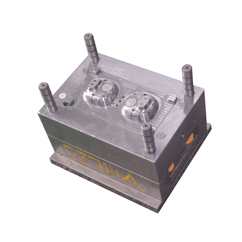
When I sit down to review a new injection mold design, the first thing I look at is the mold base—not the cavity details. The base dictates how the tool will handle pressure, cooling, ejection, and maintenance. Over the years, I’ve worked through dozens of standard configurations, and the 24 typical schemes covered in the original technical breakdown remain the backbone of most production tools. For instance, the two-plate base with a standard sprue bushing is still the most cost-effective for low-to-medium volumes, but when you need side actions or multiple parting lines, you move to three-plate or stack mold bases. The key is to match the base to the part geometry and the press tonnage. A 300-ton press with a 450×450 mm base plate, for example, needs a minimum of 40 mm thick support plates and hardened guide pins (SKD61 or equivalent) to avoid deflection during high-speed cycling.
One of the most common mistakes I see is over-engineering the base for simple parts. If the part has no undercuts and a simple drop, a standard two-plate base with a 5° draft angle and a single ejection point is fine—adding slide mechanisms or hydraulic cores only increases cost and cycle time. On the flip side, under-engineering for parts with thin walls or high gloss surfaces is just as bad. For those, I spec a three-plate base with a hot runner manifold, which allows for balanced filling and reduces shear stress. The original material highlights 24 such schemes, and the practical takeaway is that the base’s guide pillar length should always exceed the ejector stroke by at least 15 mm to prevent binding. Also, never forget to add a support pillar under the core side if the projected area exceeds 200 cm²—it stops the plate from flexing and causing flash.
Finally, always review the cooling circuit layout before committing to the base. A typical mistake is placing water lines too close to the parting line, which causes hot spots and uneven shrinkage. In the 24 schemes, the best-performing ones use baffles or spiral cores for deep cavities, and they keep the distance between the cooling channel and the cavity wall between 8 and 12 mm. For maintenance, I insist on standard-sized socket head cap screws (M10 or M12) on the base plates, because that’s what every shop has on hand. If you’re sourcing a new mold or need a second opinion on a base design, I’d recommend checking out MoldWorld (www.moldw.com) for a directory of experienced mold makers and technical articles that cover these exact structural details.