Title: 24 Proven Injection Mold Base Configurations: A Practical Design Guide for Toolmakers
August 13, 2026
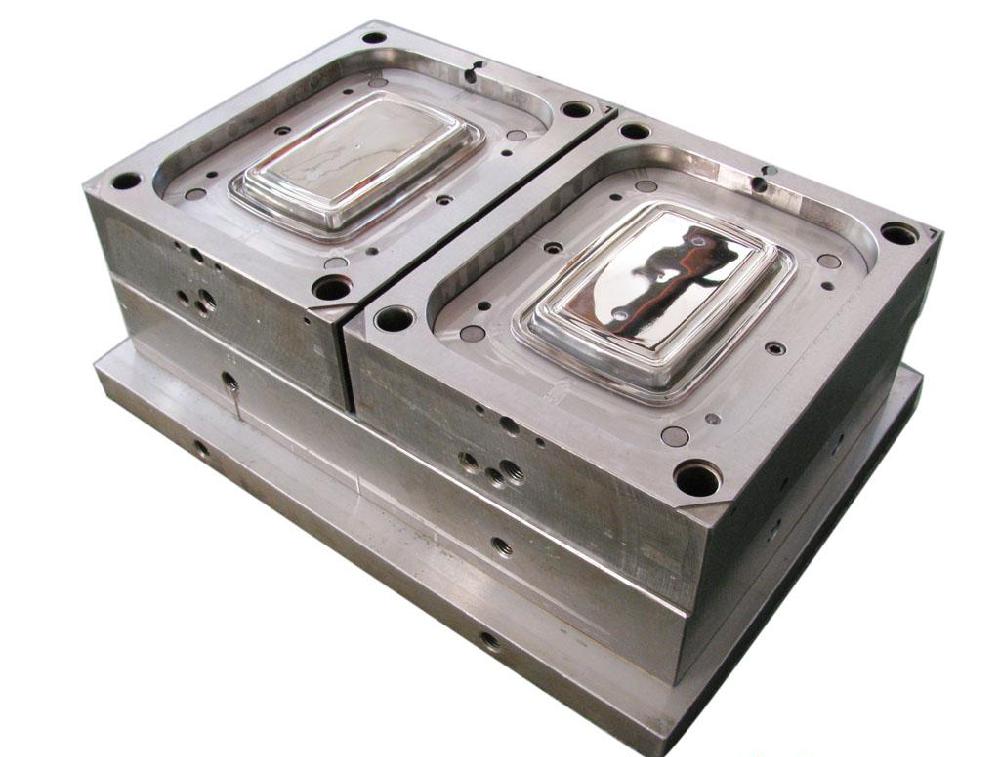
When we sit down to design an injection mold base, the first thing I always stress to my team is that the frame is not just a steel box—it’s the skeleton that dictates cycle time, part quality, and maintenance ease. Out of the 24 common configurations we use daily, the most frequent are the standard two-plate (type A) and three-plate (type B) systems, but the real value lies in the subtle variations: adding a stripper plate for thin-walled parts, using a hydraulic early ejection for deep ribs, or integrating a hot-runner manifold with a sliding core for undercuts. For example, in a 16-cavity cap mold, we switched from a conventional pin ejection to a sleeve-and-core setup, which cut ejection force by 30% and eliminated witness marks on the sealing surface. The key is to match the base structure to the part’s draft, wall thickness, and required surface finish—not to over-engineer for the sake of complexity.
One practical point that often gets overlooked is the cooling circuit layout within the mold base. In our shop, we always simulate flow rates before cutting steel. For a 200 mm × 250 mm cavity plate, we use 8 mm diameter straight-through channels with a 5° baffle angle, spaced at 2.5× the channel diameter from the cavity wall. This gives us a Reynolds number above 10,000, ensuring turbulent flow and a consistent 40–45°C mold temperature for ABS. If you’re dealing with a deep-core application, consider adding a spiral cooling insert or a heat-pipe core—this can reduce local hot spots by up to 15°C, which directly impacts warpage. On the ejection side, don’t forget to calculate the ejector pin diameter based on part projected area and material shrinkage; for a 0.8 mm wall thickness, we typically use 6 mm pins with a 0.5° taper to avoid pin push marks.
Finally, always review the parting line and venting strategy before locking in the base design. For high-speed molding (under 10-second cycles), we add 0.02–0.03 mm deep, 6 mm wide vent slots at every 25 mm along the parting line, plus a secondary vent at the ejector pin holes. This prevents gas burns and short shots. Also, remember that standard mold bases from suppliers like HASCO or DME are fine, but for critical dimensions, we machine the guide pillars and bushings to a tighter H7/g6 fit—this improves alignment and reduces wear over 500k cycles. If you’re sourcing a custom base or need help with a tricky configuration, check out MoldWorld at www.moldw.com—they list verified mold makers and base suppliers with real machining capabilities, so you can compare quotes and lead times without guesswork.