Plastic Mold Dynamic and Fixed Half Structures: From Molding Principles to Overmolding Process Essentials
August 12, 2026
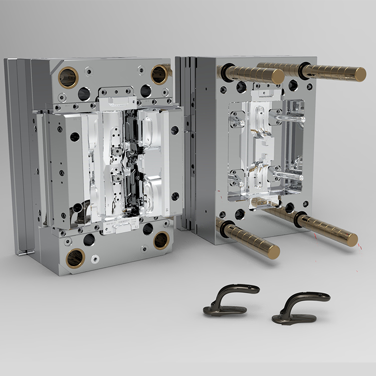
In any standard plastic injection mold, the fixed half (cavity side) is bolted to the stationary platen, while the moving half (core side) is attached to the moving platen. The fixed half typically contains the sprue bushing, locating ring, and the cavity inserts that form the outer surface of the part. The moving half carries the core, ejection system (ejector pins, sleeves, or lifters), and often the cooling channels that control the part's dimensional stability. During the clamp stroke, the two halves meet at the parting line, and the injection pressure forces the melt into the cavity. Once the part cools below its deflection temperature, the moving platen retracts, and the ejector system pushes the part off the core. A common pitfall is unbalanced cooling between the fixed and moving halves—if the moving half runs hotter, the part will stick to the cavity, causing warpage or ejection damage. For typical ABS or PC/ABS parts, a 10–15°C temperature differential between halves is acceptable, but for glass-filled nylon, that gap should be kept under 5°C to avoid sink marks.
When it comes to overmolding (also called two-shot molding or insert molding), the dynamic and fixed half interaction becomes more complex. In a rotary-table two-shot mold, the first shot (rigid substrate) is molded in the fixed half, then the moving half rotates 180° to align the substrate with the second cavity, where the soft TPE or TPU layer is injected. The critical point is the bond between the two materials: for chemical bonding, the substrate surface must be clean and free of mold release, and the melt temperature of the second material must be at least 20–30°C above the substrate's heat deflection temperature to create a weld. For mechanical interlocking, you need undercuts or through-holes in the substrate—these must be designed into the moving half's core geometry. A real-world example: molding a PP handle overmolded with a 65 Shore A TPE. If the TPE melt temperature is below 190°C, the bond fails at the peel test. Raising it to 210°C and adding a 0.3 mm deep dovetail groove in the PP substrate increased peel strength from 0.8 N/mm to 2.4 N/mm. Also, venting is critical in overmolding—the second cavity often traps air at the end of fill, so you need 0.02–0.03 mm deep vents on the moving half's parting line, otherwise you get burn marks or short shots.
Another key point is the alignment and guiding of the two halves during overmolding. Standard leader pins and bushings are not enough for two-shot molds because the rotating platen introduces lateral forces. Use tapered interlocks (with a 5–10° angle) on both the fixed and moving halves, and ensure the clearance between the core and cavity inserts is within ±0.005 mm. For insert molding (loading a metal or plastic insert manually), the moving half must have a robust insert locating system—spring-loaded pins or vacuum slots—to hold the insert in place during injection. Otherwise, the injection pressure (often 600–800 bar) will shift the insert, causing flash or broken cores. Also, always check the ejection stroke: in overmolding, the second shot often wraps around the core, so you need a positive ejection system with a longer stroke (at least 20–30 mm more than the part height) to strip the part without deformation. Finally, if you are sourcing a mold for overmolding, make sure the mold house has experience with rotary platens or index plates, and ask for a mold flow analysis that includes the two-shot sequence. For more detailed mold sourcing guidance, visit MoldWorld at www.moldw.com.