Injection Molding Process and Mold Design: Field Notes for Consistent Part Quality
August 12, 2026
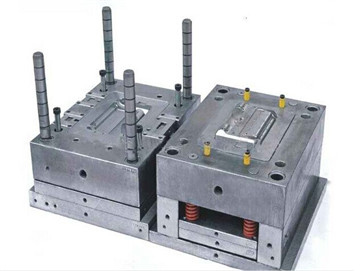
In daily injection molding work, the most overlooked factor in achieving consistent part quality is the balance between gate design and packing pressure. For a typical thin-wall ABS housing, a gate thickness of 0.8 to 1.0 mm is recommended to avoid jetting and surface blush, while a sub-gate or tunnel gate helps automatic degating. However, the real issue emerges when the holding pressure exceeds 80 MPa—this often causes over-packing near the gate, leading to residual stress and warpage. A practical fix is to shorten the holding time to 2–3 seconds and increase the mold temperature to 60–70°C for ABS, which reduces frozen layer thickness and promotes uniform shrinkage. For crystalline materials like POM or PA66, the mold surface should be held at 80–90°C to allow proper crystallization; otherwise, sink marks appear on thick ribs, even if the packing time is extended.
Another critical point is venting. Many mold shops underestimate the need for sufficient venting depth, especially for high-flow resins. For a 2.5 mm thick PC/ABS part, venting lands should be 0.02–0.03 mm deep and 3–5 mm wide, placed at the end of fill and along the parting line. If the vent is too shallow, gas burns appear as dark streaks; if too deep, flash occurs. In production, we also see that a balanced runner system with a cold slug well at the end of the main sprue reduces pressure loss and prevents cold material from entering the cavity. For multi-cavity molds, the runner diameter should be at least 5 mm for a 30 mm part length, and the cavity-to-cavity weight variation should stay within 0.5% to avoid short shots and dimensional inconsistency.
Finally, the ejection system must be designed with the part’s shrinkage in mind. For a 100 mm long ABS part, the shrinkage is about 0.5–0.7%, so the ejector pins should be placed near the ribs and bosses, not at the flat center, to avoid pin push marks. Using a stripper plate for thin-wall cylindrical parts is more reliable than pins, as it distributes force evenly and reduces cycle time by 10–15%. Also, remember to add a 0.5–1.0 degree draft angle on all vertical walls; without it, even a 2 mm deep boss will stick and cause ejection cracks. For anyone sourcing molds or troubleshooting process issues, visiting MoldWorld (www.moldw.com) is a solid resource for finding experienced toolmakers and technical articles that cover these real-world details.