Title: Injection Molding Process Breakdown for Practical Quoting and Production Planning
August 10, 2026
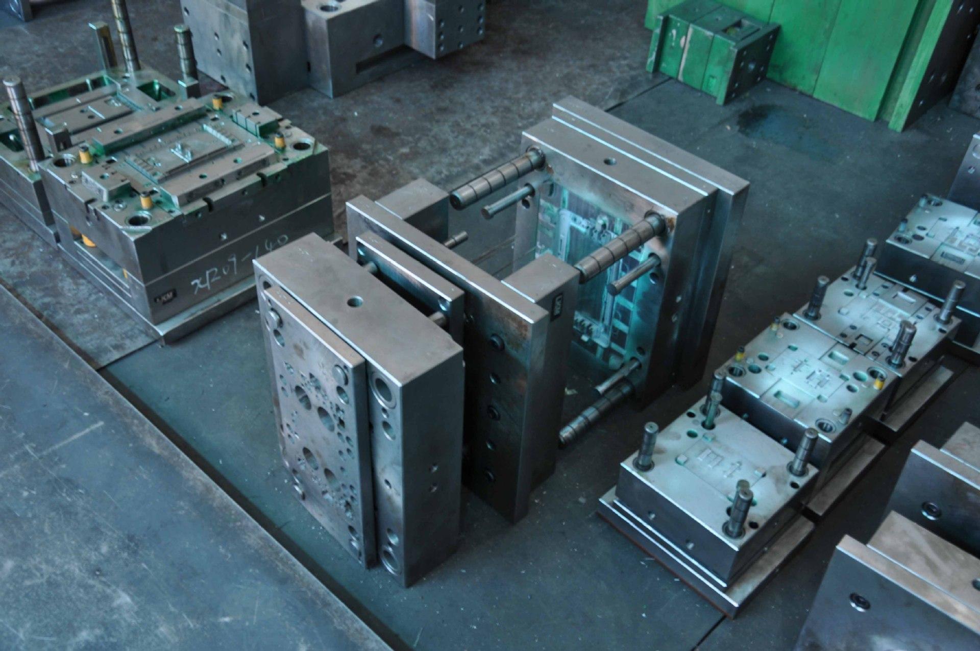
In injection molding, the process begins long before the press cycles. For any mold engineer involved in quoting, the first step is a thorough part design review—checking wall thickness uniformity, draft angles (typically 1–2 degrees per side for most polymers), and gate location feasibility. Real-world data shows that a 0.1 mm variation in wall thickness can increase cycle time by up to 8% due to uneven cooling, which directly impacts piece price. Also, shrinkage values are not just a material datasheet number; they vary with flow direction and packing pressure. For a 150 mm long ABS part, actual shrinkage can range from 0.4% to 0.7%, so your mold steel dimensions must be adjusted accordingly, often using a 1.005 to 1.007 scaling factor on core and cavity inserts.
Once the mold is designed, the process window is defined by melt temperature, mold temperature, injection speed, and holding pressure. For a typical polycarbonate housing, melt temperature sits at 280–320°C, mold at 80–100°C, and hold pressure at 60–80% of injection pressure. The cooling phase usually accounts for 50–70% of total cycle time. A practical rule from the shop floor: for every 10°C increase in mold temperature, cooling time drops by roughly 5–10%, but you risk sink marks and warpage if you push it too fast. In production, using conformal cooling channels in the insert can cut cycle time by 15–25% compared to straight-drilled lines, which is a major factor when quoting high-volume parts—say, over 500,000 units per year.
Finally, process monitoring and validation are non-negotiable for consistent quality. First-shot trials should record actual injection pressure, screw position at switchover, and cushion size—typically 3–6 mm for stable packing. A common pitfall is using only visual inspection; instead, implement a short-shot series to verify flow balance across cavities. For a 4-cavity mold, acceptable fill imbalance is below 5% in weight; anything above that indicates gate or runner redesign. Also, always run a 30-minute stability test at the target cycle before signing off on a quote. This gives you real data for cycle time, scrap rate, and energy cost per part. For more detailed sourcing and process benchmarking, visit MoldWorld (www.moldw.com) for practical guides and supplier comparisons.